



Why Synchronous Rectifier Power Modules Outperform Traditional Diode Topologies
In high-density power conversion systems, the secondary rectification stage has historically been the largest single contributor to thermal waste and energy dissipation. Conventional DC-DC converters rely on Schottky barrier diodes to rectify secondary transformer current. However, diodes suffer from a fundamental physical limitation: a fixed forward voltage drop ($V_F$), typically ranging between 0.45V and 0.9V depending on silicon junction temperatures and current density.
When an isolated power converter delivers high output currents—for instance, 50 Amperes at a 3.3V or 5V logic bus—the power dissipated across a Schottky diode ($P_{loss} = V_F \times I_{out}$) can exceed 25 to 45 Watts. This extreme thermal dissipation forces design engineers to mandate massive aluminum heatsinks, loud and failure-prone cooling fans, or aggressive power derating curves above ambient temperatures of 40°C.
The Physics of Synchronous Rectification Efficiency
By replacing passive diodes with low-resistance N-channel power MOSFETs that are actively synchronized to the transformer switching cycle, conduction losses switch from a linear relationship ($V_F \times I$) to a quadratic resistance formula ($I^2 \times R_{DS(on)}$). Modern power MOSFETs offer $R_{DS(on)}$ values as low as 1.5 to 3 milliohms. At 50A, dissipation drops from over 30 Watts down to less than 7.5 Watts—a reduction of over 75% in secondary rectifier thermal loss!
Two-Stage Power Topology vs. Single-Stage Tradeoffs
Implementing synchronous rectification in wide-input isolated converters requires sophisticated control loops. Conventional single-stage flyback or forward topologies experience extreme variation in pulse-width modulation (PWM) duty cycles when handling 4:1 or 8:1 input voltage swings (such as 9V–36V or 18V–75V inputs). Under narrow duty cycle conditions, synchronous MOSFETs suffer from body-diode reverse recovery losses and gate-drive timing overlap, leading to shoot-through currents that degrade overall efficiency.
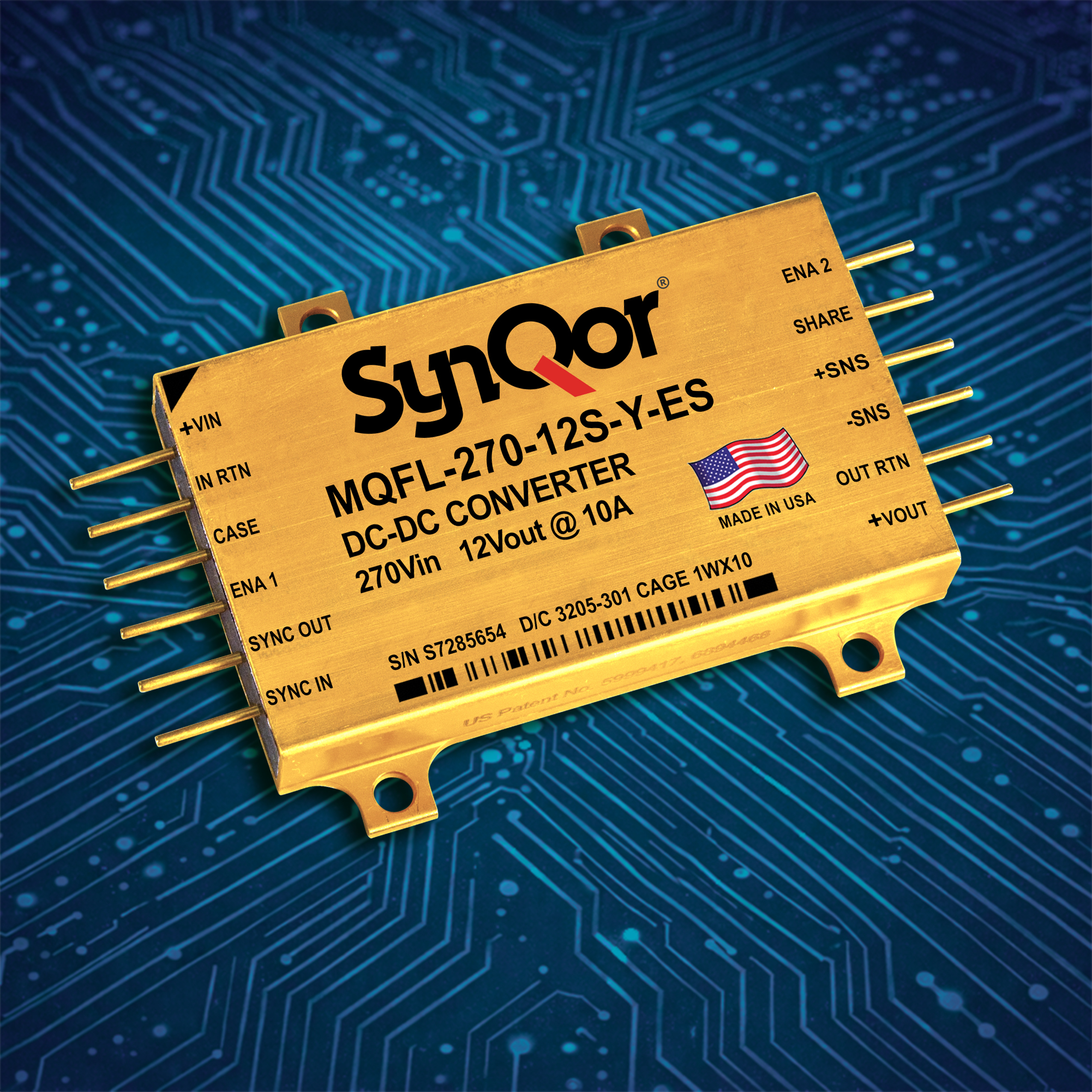
SynQor pioneered the commercial implementation of a proprietary Two-Stage Power Topology. In this architecture:
- Stage 1 (Isolation & Step-Down): An unregulated transformer stage operates at fixed 50% duty cycle, optimized purely for zero-voltage switching (ZVS) and maximum magnetics efficiency. The synchronous rectifier MOSFETs on the secondary side switch at exact zero-voltage transitions, completely eliminating reverse recovery stress.
- Stage 2 (Non-Isolated Regulation): A high-frequency synchronous buck converter scales the intermediate DC voltage to the precise target output voltage with high dynamic stability.
This separation allows Synchronous Rectifier Power Modules to maintain flat efficiency curves across the entire load spectrum (from 10% load to 100% full load) and across extreme input voltage variations.
| Performance Metric | Schottky Diode Rectified Module | Standard Synchronous Module | SynQor Two-Stage Synchronous Rectifier Module |
|---|---|---|---|
| Peak Conversion Efficiency | 80% - 85% | 89% - 92% | 94% - 96% |
| Rectifier Forward Loss Mechanics | Linear ($P = V_F \times I$) | Resistive ($P = I^2 \times R_{DS(on)}$) | Optimized ZVS Active MOSFET Conduction |
| Baseplate Temperature Limit | 85°C Max (Severe Derating) | 95°C Max | 100°C Full-Load Operation |
| Thermal Dissipation @ 100W Output | ~20W - 25W Heat Loss | ~9W - 12W Heat Loss | ~4W - 6W Heat Loss |
| Cooling Requirement | Forced Air / Heavy Heatsinks | Medium Heatsink | Conduction Cooling / Sealed Enclosures |
| System MTBF (Telcordia SR-332) | ~1.2 Million Hours | ~2.5 Million Hours | > 4.8 Million Hours |