0%

Modern power electronics are becoming denser, faster, and less forgiving of electrical noise. Grand View Research identifies sustained growth in the global EMI shielding market, driven by electric vehicles, telecommunications, medical equipment, and industrial automation. MarketsandMarkets reports similar expansion across electromagnetic compatibility technologies. These trends point to a practical concern: compact converters must control interference without sacrificing efficiency, thermal performance, or serviceability.

Transient Half-Brick EMI Filters address this challenge at the power-interface level. Their half-brick form factor fits established converter layouts, while filtering components help reduce conducted noise from rapid switching events. A poorly controlled transient can travel through input cables, disturb nearby sensors, or trigger repeated equipment resets. The problem may appear only during startup, load changes, or fault recovery. That makes laboratory testing essential.

Engineers commonly evaluate insertion loss, differential-mode attenuation, common-mode attenuation, temperature rise, and impedance behavior. IEC 61000-4-4 provides a recognized framework for electrical fast transient testing, while CISPR 32 supports emissions assessment for multimedia equipment. These standards do not remove design uncertainty. They expose it.

No filter is magic.

A reliable selection process considers converter topology, switching frequency, source impedance, grounding, cable length, and enclosure structure. In my experience, an attractive datasheet curve can mislead when the installation differs from the test fixture. Transient Half-Brick EMI Filters therefore deserve attention not merely as replacement components, but as integrated noise-control tools. Their value depends on verified performance, realistic operating conditions, and honest review of compromises between attenuation, size, cost, and power loss.
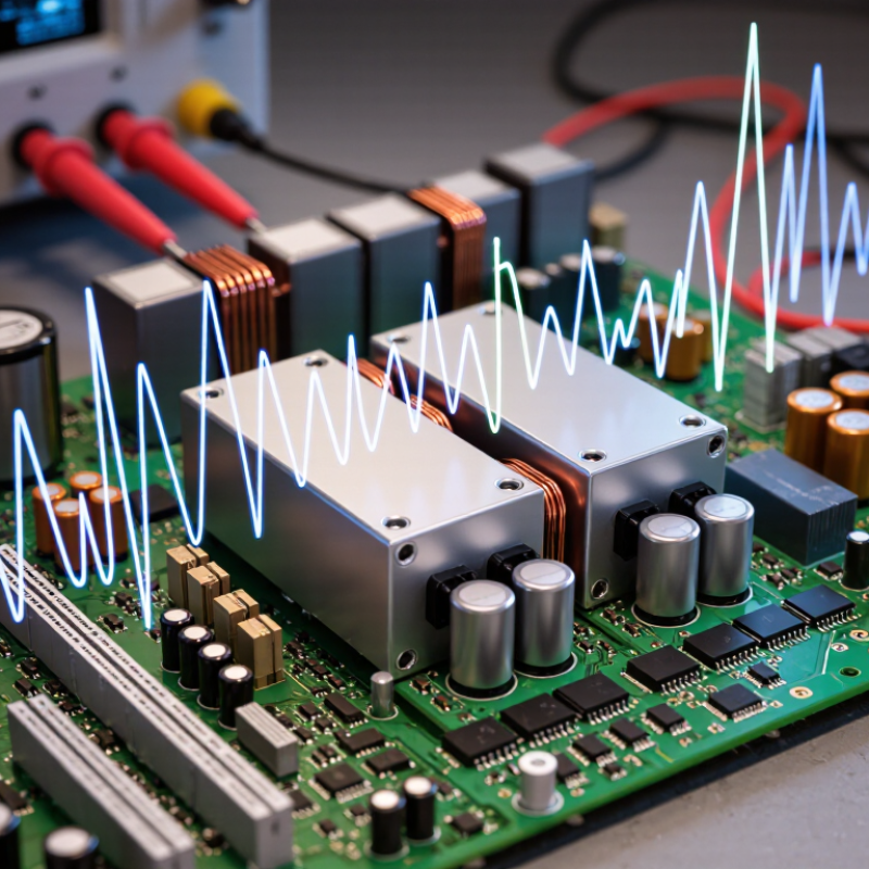
Why Choose Transient Half Brick EMI Filters?

What Are Transient Half Brick EMI Filters?

Transient half brick EMI filters are compact power-interface modules built for half-brick DC-DC converter systems. They reduce unwanted electrical noise before it travels through power cables or reaches sensitive circuits. Their housing follows a common half-brick footprint. This simplifies mechanical integration.

Inside, the filter may combine common-mode chokes, differential-mode inductors, capacitors, damping networks, and transient suppression devices. Each part has a specific role. Inductors resist rapid current changes. Capacitors redirect high-frequency noise. Suppression components limit short voltage spikes, when included in the design.

However, an EMI filter is not automatically a complete surge protector.

In practical power designs, engineers place the filter close to the converter input. Short connections matter. Long traces can add parasitic inductance and weaken transient performance. Selection should consider input voltage, continuous current, peak current, insertion loss, thermal rise, and creepage distance. A filter rated for steady current may still respond poorly to repeated load steps. That detail is easy to miss.

Measurement remains essential. A bench test with an oscilloscope can reveal ringing that calculations overlook. A spectrum analyzer can show whether noise moved into another frequency range.

Installation quality affects results. Grounding, cable routing, and enclosure layout often matter as much as the filter itself.

I have found that “plug-and-play” assumptions can create avoidable problems. Sometimes, a smaller filter with better placement performs more reliably than a larger one.

How Do Transient Half Brick EMI Filters Work?

Why Choose Transient Half Brick EMI Filters?

How Do Transient Half Brick EMI Filters Work?

A transient half brick EMI filter controls unwanted electrical energy before it reaches sensitive equipment. Its half-brick footprint fits many compact power-conversion systems. Inside, inductors resist rapid current changes, while capacitors provide a lower-impedance path for high-frequency noise. Together, these parts reduce conducted emissions on input and output lines.

The filter responds to two main noise types. Common-mode noise travels in the same direction along multiple conductors. Differential-mode noise moves between paired conductors. Separate filtering paths address these behaviors. During a sudden voltage spike, suppression components can limit the peak and slow its rise. The filter then helps the converter recover without excessive ringing or interference.

Real performance depends heavily on circuit layout. Short connections, controlled grounding, and suitable capacitor ratings matter. Small parasitic inductances can weaken an otherwise careful design. A common mistake is choosing a filter by current rating alone. That is not enough. Engineers should check insertion loss, transient amplitude, operating temperature, load behavior, and source impedance. Measurements with an oscilloscope and EMI test equipment reveal problems that calculations may miss. In practice, the first design is rarely perfect. A slightly larger filter may improve stability, yet it can also increase cost, leakage current, or startup delay. Careful testing remains essential.

Which Electrical Problems Do They Address?

Why Choose Transient Half Brick EMI Filters?

Which Electrical Problems Do They Address?

Fast switching circuits can create sharp voltage and current changes. These transients travel through power lines and nearby wiring. A transient half brick EMI filter helps reduce this unwanted electrical energy before it spreads through the system.

The filter mainly addresses conducted electromagnetic interference. Differential-mode noise can appear between positive and negative supply lines. Common-mode noise can travel along both lines toward the chassis or ground. Without control, this noise may cause sensor readings to drift, communication errors, false resets, or audible interference in power equipment. It can also make pre-compliance testing unexpectedly difficult.

Half-brick construction suits compact power converters and modular cabinets. Its standardized size can simplify installation, airflow planning, and service access. During bench testing, engineers should check noise under real load conditions, not only at idle. Switching frequency, cable length, grounding, and enclosure design can change the result.

The filter is not magic.

Poor wiring can weaken its performance. A long connection between the filter and converter may act like an antenna. Incorrect current ratings can create heat, voltage drop, or premature failure. Transient protection also needs careful coordination with fuses, shielding, and grounding. In some designs, filtering one frequency range may leave another disturbance untouched. That limitation deserves honest review before production.

What Design Features Improve Their Performance?

Why Choose Transient Half Brick EMI Filters?

Design features largely determine how well a half-brick EMI filter controls noise and survives fast electrical changes. A compact half-brick housing fits many modular power systems, but size alone proves little. Engineers should examine insertion loss across the actual switching range, not just one attractive frequency. Separate common-mode and differential-mode filtering paths can reduce noise from cables and converter switching nodes. Low-parasitic capacitors help maintain performance at higher frequencies. Small details matter.

A strong design also controls transient energy without creating excessive ringing. Damping networks can limit resonance between inductors, capacitors, and the converter input impedance. Some applications may require a dedicated transient suppressor or active clamp beside the filter. A filter alone is not a complete surge protector.

Thermal spacing, creepage distance, and insulation ratings support dependable operation in crowded assemblies. Shielded construction can reduce magnetic coupling, while short internal connections preserve the intended impedance.

Bench testing often reveals problems that simulations miss. Load steps, cable length, source impedance, and mounting hardware can change the result. Measure conducted emissions before and after installation. Check temperature rise under continuous current. Watch the waveform closely. A filter that performs well at room temperature may behave differently near its rated limit. Engineers should also question whether the chosen attenuation creates startup delay or control-loop instability. That trade-off is real, and careful validation improves reliability.

How Should Engineers Select and Apply Them?

Why Choose Transient Half Brick EMI Filters?

As power density rises, transient half brick EMI filters offer compact protection for DC-DC converters. The IEA’s Electricity 2024 report estimates that data centers used about 460 TWh globally in 2022. Demand may exceed 1,000 TWh by 2026. More power electronics also means more switching noise and harsher transient conditions. Engineers should select filters by measured voltage, continuous current, switching frequency, and expected pulse energy. Do not choose by package size alone.

Check insertion loss across the real noise spectrum, not only at one test frequency. Confirm the filter’s voltage rating includes startup overshoot and abnormal input events. IEC 61000-4-4 defines electrical fast transients up to 4 kV in applicable test conditions. IEC 61000-4-5 also addresses surge immunity. The filter must work with the converter’s input impedance. Otherwise, unwanted resonance may appear. A damping network can help, but it adds heat and losses. Small errors matter.

Tips: Place the filter close to the converter input. Keep noisy and quiet traces physically separated. Use short, wide return paths. Measure conducted emissions with the final enclosure, cable length, and load. A filter that performs well on the bench may fail after installation. I would also check temperature rise at maximum load. This step is often skipped. Review the oscilloscope waveform, then repeat the test after thermal cycling. Perfect calculations are useful, but field evidence should decide.

FAQS

What is a transient half-brick EMI filter?

It is a compact power-interface module for half-brick DC-DC converter systems. It reduces unwanted electrical noise and limits short voltage spikes. The housing fits a familiar converter footprint. Mechanical integration becomes easier.

How does the filter reduce electrical noise?

Inductors resist rapid current changes. Capacitors redirect high-frequency noise away from sensitive circuits. Common-mode paths handle noise moving through conductors together. Differential-mode paths handle noise moving between paired conductors. The result is lower conducted interference.

Does this filter replace a complete surge protector?

Not always. A filter may limit short spikes, but its protection range depends on the design. Check voltage ratings, pulse energy, and suppression components carefully. Do not assume complete protection. That assumption can fail.

Where should engineers install the filter?

Place it close to the converter input. Keep connections short and wide. Long traces add unwanted inductance and weaken transient performance. Separate noisy traces from quiet traces. Grounding still matters.

Which specifications matter during filter selection?

Review input voltage, continuous current, peak current, switching frequency, and expected pulse energy. Check insertion loss across the actual noise spectrum. Also examine thermal rise, leakage current, startup delay, and creepage distance. Current rating alone is insufficient.

How can engineers test a transient half-brick EMI filter?

Use an oscilloscope to inspect voltage spikes, ringing, and recovery behavior. Use suitable EMI equipment to check conducted noise. Test with the final cables, enclosure, and load. Bench results can mislead.

Can a larger filter always provide better performance?

No. A larger filter may improve attenuation or stability. It can also increase cost, heat, leakage current, or startup delay. A smaller filter with better placement may work more reliably. Size is not performance.

What common design mistakes should engineers reconsider?

Choosing only by current rating is a common mistake. Ignoring source impedance can create unwanted resonance. Skipping temperature testing may hide problems at maximum load. Repeat measurements after thermal cycling. The first design is rarely perfect.

Conclusion

Transient Half-Brick EMI Filters are compact power-conditioning components designed to reduce electromagnetic interference while helping protect sensitive electronic systems from short-duration voltage disturbances. Their half-brick form factor supports efficient integration into power converters, industrial controls, telecommunications equipment, and other space-constrained applications. By combining filtering elements with transient suppression functions, they can attenuate unwanted common-mode and differential-mode noise, limit disruptive voltage spikes, and support cleaner power delivery.

Their performance depends on coordinated design features such as low parasitic inductance, suitable capacitance, effective grounding, high-frequency suppression paths, and adequate thermal and voltage margins. These features help address conducted emissions, switching noise, surge-related stress, ringing, and instability caused by rapid changes in current or voltage. Engineers should select Transient Half-Brick EMI Filters according to system voltage, current, transient energy, frequency range, insertion-loss needs, safety requirements, and available space. Proper placement, short connection paths, careful grounding, and testing under real operating conditions are also essential for achieving reliable and consistent results.


Ethan

Ethan

Ethan is a dedicated marketing professional with a strong understanding of the company’s products, customers, and evolving market needs. Through a combination of strategic thinking, industry research, and clear communication, he helps connect practical product value with the people and businesses......